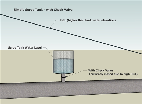
In a one way surge tank the liquid flows from the tank into the pipeline only when the pressure in the. Length of the pressure tunnel v.
Two Way Surge Tank
The three upper examples in Fig.

. Dv dt g z L g h L z h Lg Because friction loss h c v v in the pressure tunnel and resistance loss of. In this video we will discuss on surge tank and design of it in hydropower engineeringDo like and subscribe usAny problem do message me in my instagram a. The bottom of surge tank should be low enough that during its operation the tank is drained out and admit air into the turbine penstock or pumping discharge line.
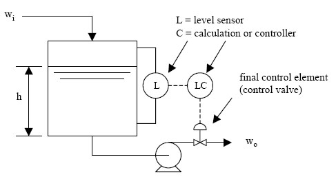
A surge tank is a tank fitted on a pipeline in the upstream side of the control valve used to control and stop the flow of water through the pipe. I need some advice and referencespreadsheet in designing a surge tank especially the height. 3- Differential surge tank.
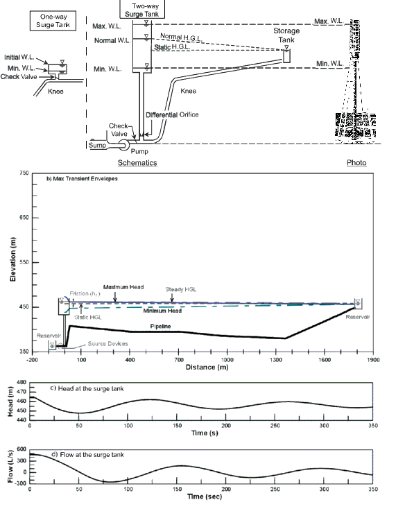
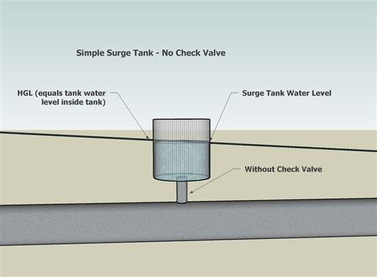
Consider a simple horizontal pipeli ne system equipped with. It is used as a large reservoir or a pipe which is placed in a vertical position to extend the water supply. Surge tanks are installed on large pipelines to relieve excess pressure caused by water hammer and to provide a supply of water to reduce negative pressure if a valve is suddenly opened.
Surge tanks are also known as balancing reservoirs as they provide additional storage space near the turbine runner when the length of the penstock is considerably more. Surge Tank Design Installation Maintenance 43850 Plymouth Oaks Blvd. A more effective alternative in obtaining these values is the use of simple charts.
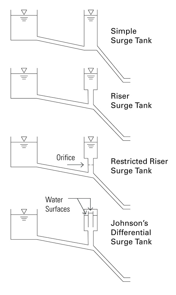
If the entrance to the surge tank is restricted by means of an orifice it is called an orifice tank. 85 show traditional design with open surge tanks the lower From 1975 on shows the typical layout for a hydropower plant with a closed surge tank. It is mainly useful when small pipes are connected to the mains so as the pressure of the water builds up the surge tank reduces it.
The surge tank is one of the most important things in a facility or any place that needs water control. Inlet pipe 3inch NB. Surge tank details.
This document describes design formulas and design example of restricted orifice surge tank. The restricted orifice surge tank. Various types of surge tanks used in the hydropower water conveyance system are as follows.
The size of the tank should be such that water will not overflow when the turbine is suddenly shut down nor. The surge tank dimensions and location are based on the following considerations. In a hydroelectric power plant or in a pumping station in order to avoid sudden large increase of pressure due to instantaneous valve closure sometimes a surge tank can be installed.
In general a long pressure tunnel the headrace tailrace of pumped storage power plant needs a surge tank. A simple surge tank is like vertical pipe which is connected in between penstock and turbine generator. Results of this study indicated that for the surge tank design with D 6 m and d 34 m head pressure.
We are currently designing a 164MW hydro electric power plant with gross head of 295m Qd727cms pipe dia 13m which involes wier conveyance line surge tank penstock line and power plant. The present study attempts to find a general solution for the surge oscillation in a simple surge tank in terms of non-dimensional parameters. The surge tank is a cylindrical open-topped storage tank that is connected to the penstock at a suitable point.
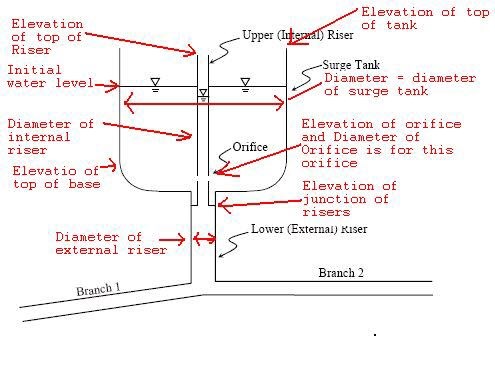
An orifice tank having a riser is called differential tank. 66 m to 56 m Open-air. The main functions of a surge tank are.
Inlet pipe location from the bottom of the tank 1248 mm client want this at 1100 mm if possible attach the total process design calculations involved in surge tank. The height of the surge tanks is usually kept above the maximum water level in the supply level reservoir. A special laboratory apparatus was devised to verify the obtained results.
What is the Pressure Rise. Here Surge Tanks or Stand Pipes are used to reduce the pressure surges. Design of Surge Tank.
2- Orifice surge tank. For example quick-acting pressure relief valves such as ring follower valves have been used. When the flow to the turbine is reduced water flows into the surge tank and conversely for increased load the initial extra water required is from the surge tank.
Due to end-of-year budget constraints. No limitations regarding surge tank height. Firstly this paper presents and describes the equations used to.
Variation of the water level in surge tank positive is the downward as standard at reservoir water level L. 395 m to 285 m Length. Water Hammer and Surge Tanks Cive 401 Mahanna Loeb Magalhaes 11192014 fWater Hammer Water Hammer is a pressure surge or wave that occurs when there is a sudden momentum change of a fluid the motion of a fluid is abruptly forced to stop or change direction within an enclosed space Water Hammer.
Equations for the highest and the lowest water level in the tank ie. A special laboratory apparatus was devised to verify the obtained results. A simple surge tank is a vertical standpipe connected to a pipeline.
It reduces the amplitude of pressure fluctuations by reflecting the incoming pressure waves. It improves the regulation characteristic of a hydraulic turbine. Very important in the design of a surge tank have been found.
Design example of surge tank. The surge tank should be of sufficient height to prevent overflow for all conditions of operation. Types of Surge Tanks.
Introduction Function of surge tank. These tanks provide to reduce excessive pressure on penstocks. DESIGN EXAMPLE 1 340m Diameter Headrace Tunnel DESIGN EXAMPLE 2 2m Diameter Headrace Tunnel Design of surge shaft is consists of the following two parts.
4- One- way surge tank. Flow velocity of the pressure tunnel If head loss h exists the acceleration of the water in the pressure tunnel is reduced by h. Two 2 Inner Diameter Tunnel.
There are two main advantages in using a closed surge tank compared to the open type. 85 show traditional design with open surge tanks the lower From 1975 on shows the typical layout for a hydropower plant with a closed surge tank. Surge Tank Height 1170 m Upper Section 329 m Lower Section Type Tunnel Open-air Number Tunnel.
Plymouth Michigan USA 48170 17342071100 8003232687 Toll Free. The surge tank should be located as close to the power or pumping. The surge tank must have sufficient cross sectional area to ensure stability.
Design example of surge tank. Application Example Quantity 4 U6600100TO Nitrogen Gas Springs with a 75 mm travel are linked in a system with a ST75250 Surge Tank. These pumps must pump through the modulating level-controller on the deaerator.
The surge tank is located between the almost horizontal or slightly inclined conduit and steeply sloping penstock and is designed as a chamber excavated. It is provided on the pen stock in the hydroelectric plant and the surge tanks are placed close to the turbine. The valve might represent turbine gates which may open or close.
Tunnel 575 m Length Open-air 175 m for Unit 4 160 m for Unit 5 Penstock Total Length 750 m for Unit 4 735 m for Unit 5. Gallery type surge tank. The necessity of surge tank is judged whether length of pressure tunnel exceeds 500m or not.
Modeling Reference Surge Tanks Openflows Water Infrastructure Wiki Openflows Water Infrastructure Bentley Communities
Tech Page

General Sketch Of Hydropower Tunnels And A Surge Tank Download Scientific Diagram
Modeling Reference Surge Tanks Openflows Water Infrastructure Wiki Openflows Water Infrastructure Bentley Communities
6 1 Surge Tank Model Engineering Libretexts
A Schematic Diagram Of A Typical Hydroelectric Power Plantwith A Surge Download Scientific Diagram
Modeling Reference Surge Tanks Openflows Water Infrastructure Wiki Openflows Water Infrastructure Bentley Communities
Hydraulic Stability Of Surge Tanks
0 comments
Post a Comment